This topic describes how to customize different aspects of the diagram in Entity Developer.
In Entity Developer, you can customize the following aspects of the diagram:
| • | General - allows customizing the general parameters of the diagram; |
| • | Notation - allows customizing the notation of the diagram; |
| • | Page - allows customizing the page parameters of the diagram; |
| • | Print - allows customizing the printing parameters of the diagram. |
The corresponding procedures are described below.
|
|
Changes introduced through the procedures described below are applicable to the way the entire application works rather than to an individual diagrams. These changes are applicable only to newly-created diagrams. To apply the global defaults to an existing diagram, right-click the diagram, select Options and, in the Options dialog box, select the appropriate tab and click Default.
|
To customize the general parameters of the diagram, perform the following sequence of actions:
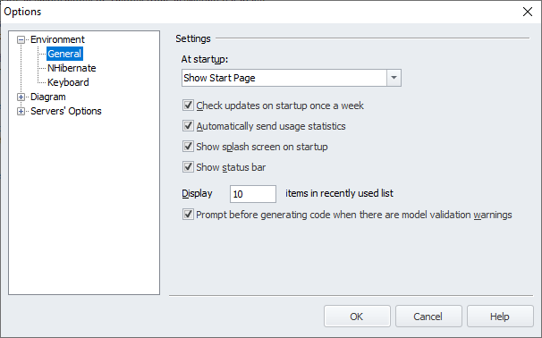
| 1. | From the application's main menu, select Tools and then select Options. The Options dialog box is displayed: |
| 2. | Expand the Diagram node and, under it, select General. The Settings page is displayed: |
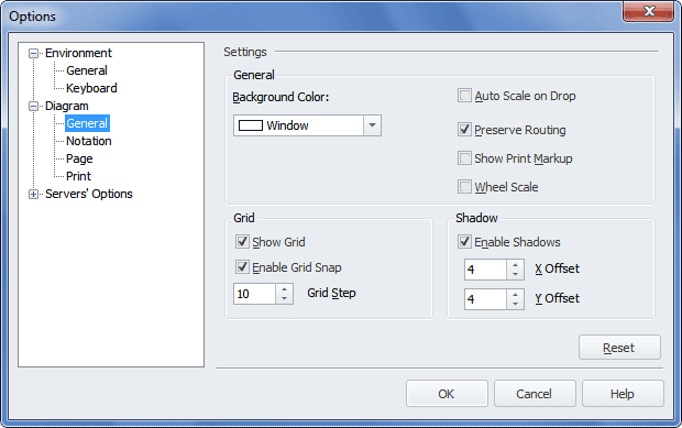
| 3. | In the General area of the Settings page, define or change the following parameters: |
| o | Background Color - select the background color for the diagram; |
| o | Auto Scale on Drop - select this check box to scale the diagram automatically to fit all its shapes when database objects are dropped on to the diagram; |
| o | Preserve Routing - keep this check box selected to preserve the routing of relation links on the diagram; |
| o | Show Print Markup - select this check box to have print markup displayed on the diagram; |
| o | Wheel Scale - select this check box to enable the use of the mouse scroll wheel to scale the diagram. |
| 4. | In the Grid area of the Settings page, define or change the following parameters: |
| o | Show Grid - keep this check box selected to have the grid displayed on the diagram; |
| o | Enable Grid Snap - keep this check box selected to have the shapes snapped to the grid when the shapes are dragged; |
| o | Grid Step - enter the value of the grid cell in pixels. |
| 5. | In the Shadow area of the Settings page, define or change the following parameters: |
| o | Enable Shadows - keep this check box selected to have shadows displayed on the diagram; |
| o | X Offset - enter the value of the horizontal offset of the shadow; |
| o | Y Offset - enter the value of the vertical offset of the shadow. |
| 6. | (Optional) To reset the parameters available on this page to their default values, click Reset. |
|
To customize the notation parameter of the diagram, perform the following sequence of actions:
| 1. | From the application's main menu, select Tools and then select Options. The Options dialog box is displayed. |
| 2. | Expand the Diagram node and under it select Notation. |
The Default Document Settings page is displayed:
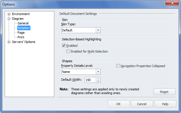
| 3. | From the Skin Type drop-down menu in the Skin area, select a skin for the diagram. |
| 4. | In the Selection-Based Highlighting area, keep the Enabled check box selected to enable the selection-based highlighting functionality and select the Enabled for Multi-Selection check box to enable the selection of several objects. For more information on this functionality, refer to the Selection-Based Highlighting topic. |
| 5. | In the Shapes area, from the Property Details Level drop-down menu, select the required value and, to keep navigation properties of all entities within the diagram collapsed, select the Navigation Properties Collapsed check box. |
| 6. | Change the Default Width value, if necessary. The new value of this option will be applied to classes, complex types and enum types newly created in the diagram area. |
| 7. | (Optional) To reset the parameters available on this page to their default values, click Reset. |
|
To customize the page parameter of the diagram, perform the following sequence of actions:
| 1. | From the application's main menu, select Tools and then select Options. The Options dialog box is displayed. |
| 2. | Expand the Diagram node and under it select Page. |
The Page Settings page is displayed:
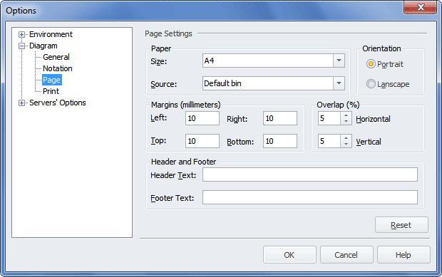
| 3. | Using the appropriate drop-down lists in the Paper area, select the size and source of the paper. |
| 4. | In the Orientation area, select the orientation of the page. |
| 5. | Using the appropriate boxes in the Margins area, specify the margins of the page. |
| 6. | Using the appropriate boxes in the Overlap area, specify the values for the horizontal and vertical overlap. |
| 7. | In the appropriate boxes in the Header and Footer area, enter the text for the header and/or the footer. |
| 8. | (Optional) To reset the parameters available on this page to their default values, click Reset. |
|
To customize the print parameter of the diagram, perform the following sequence of actions:
| 1. | From the application's main menu, select Tools and then select Options. The Options dialog box is displayed. |
| 2. | Expand the Diagram node and under it select Print. The Print Settings page is displayed: |
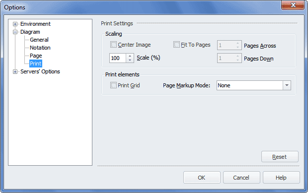
| 3. | To center the image on the page, in the Scaling area, select the Center Image check box and, if applicable, enter the value in the Scale (%) box. |
| 4. | To fit the diagram onto several pages, select the Fit To Pages check box and, if needed, in the Pages Across and Pages Down boxes, specify the number of pages, onto which the diagram should be fitted by its width and height respectively. |
| 5. | To have the grid printed, in the Print elements area, select the Print Grid check box. |
| 6. | To have the page markup symbols printed, from the Page Markup Mode drop-down list, select a value other than None. The following two values are available: Page Margins (Page margin borders are printed as a dotted line. Only the borders of the margins that should be cut off are printed, for example, for the top left page, only the right and bottom borders are printed) and Full Markup (Overlapping borders markup is printed, where needed, to help you to glue diagram pages together). |
| 7. | (Optional) To reset the parameters available on this page to their default values, click Reset. |
|
Send feedback on this topic
© 2008 - 2026 Devart. All rights reserved.
 General Diagram Parameter Customization