After the two required connections are created, we can proceed to customizing the data flow components.
In this example, we will also show how to create and use a variable. To create a variable perform the following steps:
| 1. | Right-click the design surface and then click Variables. |
| 2. | The Variables window is displayed. On the Variables window toolbar click the Add Variable button. |
| 3. | A new variable is created and displayed in the window. Rename it as required, then in the Properties window set the variable properties. |
In this example we call the variable 'AccountName' and set the following properties:
ValueType = String
Value = GenePoint
other properties are left set to their default values.
Now we proceed to customizing the Devart Salesforce Source.
| 1. | Double-click the Devart Salesforce Source data flow object. |
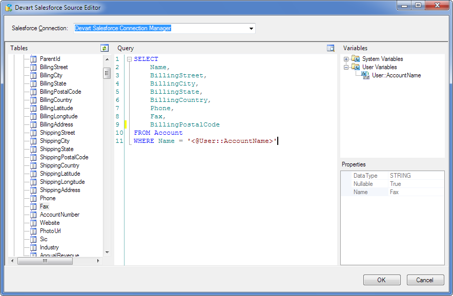
| 2. | The Devart Salesforce Source Editor dialog box is displayed. Select the created Devart Salesforce Connection Manager in the Salesforce Connection list. |
| 3. | Drag the required table (in our example we use the Account table) from the Tables area to the Query area:
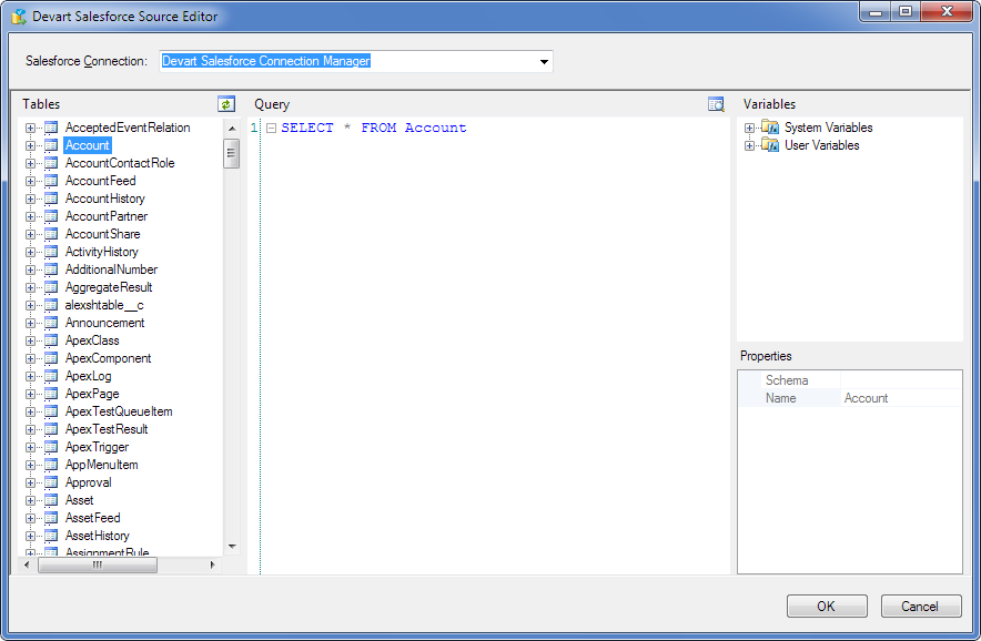 |
| 4. | Then we add a WHERE clause and drag the variable we have previously created from the User node of the Variables area to the Query area. |
| 5. | We may also edit the query in such a way that only the necessary columns are selected. Thus, we get the following query:
 |
| 6. | Click the Preview Data button to view the result of the query execution. The Preview Data window is displayed:
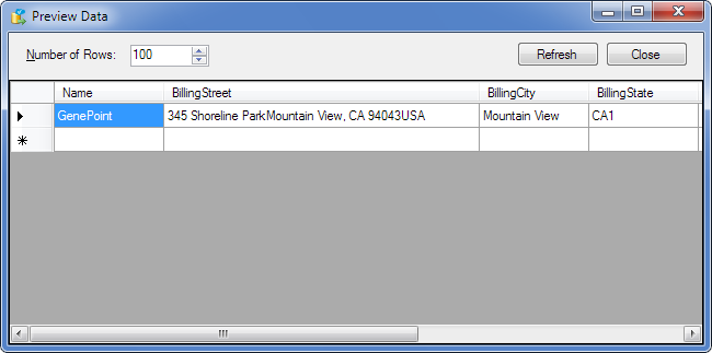 |
| 7. | Click Close to return to the Devart Salesforce Source Editor dialog box. |
| 8. | In the editor dialog box click OK. |
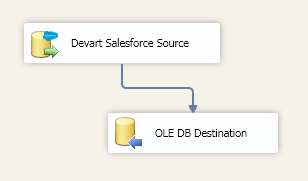
If all options are set correctly, the red marker on the data flow object disappears. Connect the two data flow objects with a Data Flow path and proceed to customizing the OLE DB Destination:
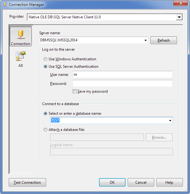
| 1. | Right-click the OLE DB Destination data flow object. The Connection Manager tab of the OLE DB Destination Editor dialog box is displayed.
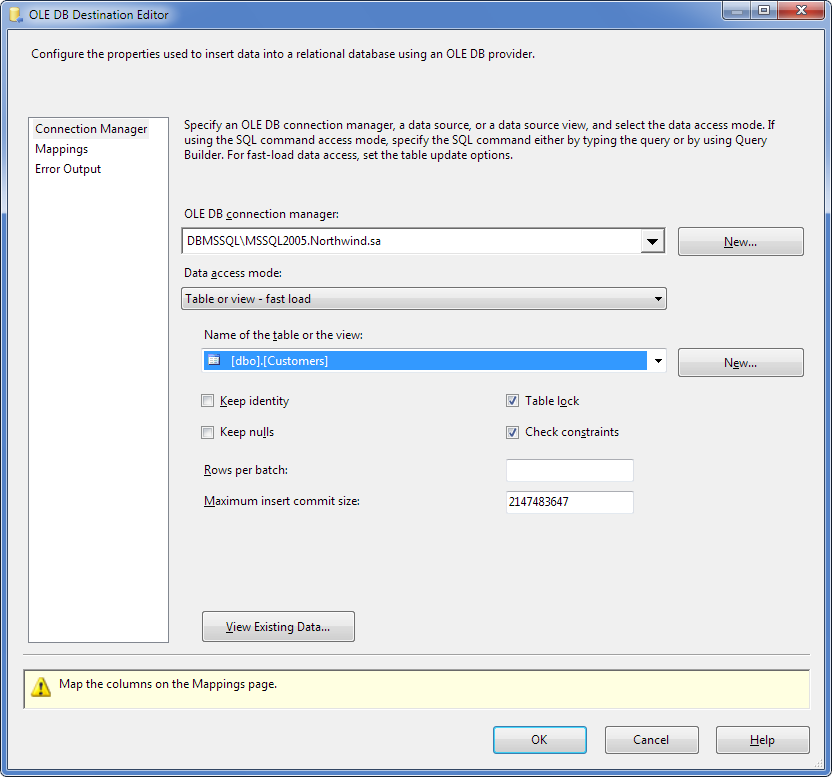 |
| 2. | Specify the following settings in this tab: |
| 3. | Select the required connection in the OLE DB connection manager drop-down list; |
| 4. | Select Table or View in the Data access mode list; |
| 5. | Select the required database object name in the Name of the table or the view drop-down list. |
| 6. | Switch to the Mappings tab. |
| 7. | SSIS automatically maps columns having the same names. If necessary, specify mapping between the source and destination columns either using the Input Columns drop-down lists, or just by drawing lines between the corresponding columns: |
| 8. | Switch to the Error Output tab.
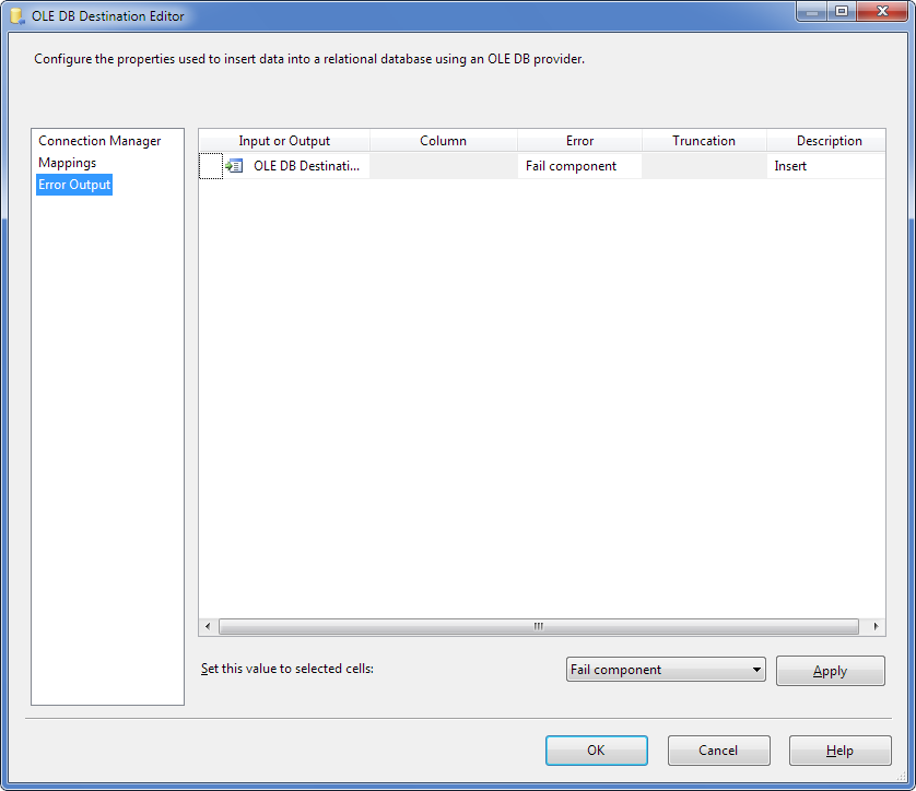
This tab allows you to specify in what way component failure should be treated; the following options are available: Fail component, Redirect row, Ignore failure. |
| 9. | After all options are set, click OK. |
Make sure that the red marker is absent on the OLE DB Destination data flow object.
Right-click the design area and then click Execute Task. The green marks on the data flow objects indicate that the data flow process is completed successfully:
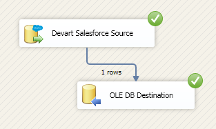
|
 Adding Data Flow Components