Creating model using Model-First approach
Create a model using the Model-First approach
This section explains how to create a model using the Model-First approach. To create a model:
1. In Solution Explorer, right-click your project name.
2. Select Add > New Item.
Note
In the standalone application, on the Entity Developer toolbar, click Create New Model.
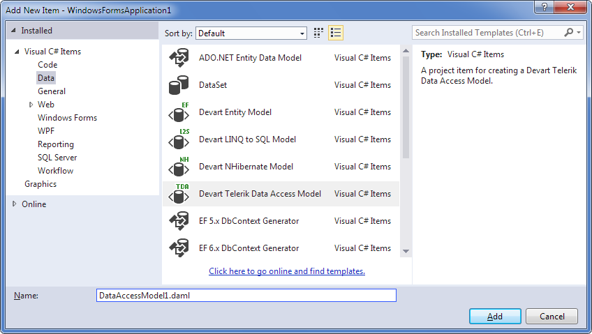
3. In the Add New Item dialog, under Installed Templates, select Data.
4. In the center pane, select Devart Telerik Data Access Model.
Note
In the standalone application, in the New Model dialog, select Devart Telerik Data Access Model and click Create.
5. Click Add.
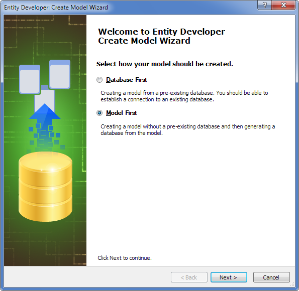
6. On the Create Model Wizard welcome page, select Model First and click Next.
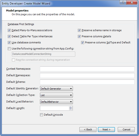
7. On the Model properties page, select identity from the Name dropdown list in the Default Identity Generator area, configure the settings for your model, and click Next.
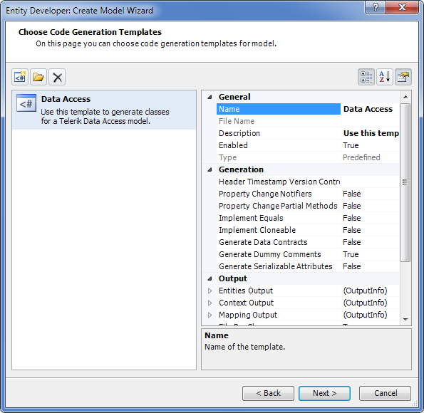
8. The Choose Code Generation page allows you to select code generation templates to add to the new model. By default, this page contains the most frequently used template. The properties area allows you to configure the properties of the selected template. Use the three buttons at the top to add more templates from the gallery, add existing templates from disk, or remove templates from the list.
9. Click Add template.
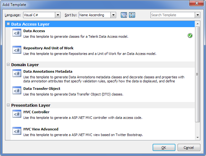
10. In the Add Template dialog, select the required template and click OK. The selected template is added to the list on the Choose Code Generation page along with all related templates.
11. After adding all required templates to the list on the Choose Code Generation page, click Next.
12. On the final window of the wizard, click Finish.
After the empty diagram is displayed, you can create the required classes, associations, and inheritances.
The descriptions of procedures for creating classes, associations, and inheritances are provided in the following sections.
Create a class
This procedure explains how to create a class. For this example, we’ll create the Blog class.
Note
Before creating classes, check that identity is selected as the default generator in your model properties. In the Model Explorer window, right-click your model, select Properties from the shortcut menu, and, in the Properties window, verify that Default Identity Generator is set to identity.
1. Right-click on the empty diagram and select New Class from the Add submenu.
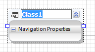
2. Click the default class name (Class1), type Blog, and press Enter.
3. Right-click the created class and select New Property from the Add submenu.
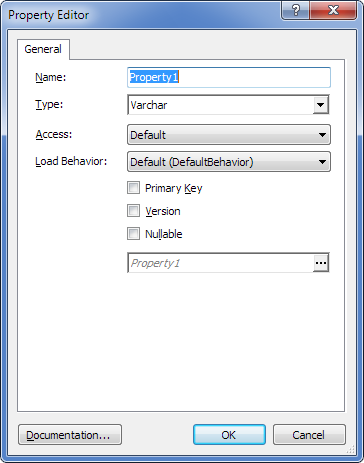
4. In the Name box, enter the property name (BlogID).
5. From the Type dropdown list, select Int64.
6. Select the Primary Key checkbox.
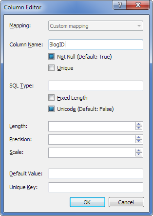
7. Optional: To change the default parameters of the database column to which this property is mapped, click the ellipsis (…) in the Column field and, in the Column Editor window, enter the desired values and click OK.
8. Click OK.
9. To create the second property (BlogTitle), right-click the created class and select New Property from the Add submenu.
10. In the Name box, enter the property name (BlogTitle).
11. From the Type dropdown list, select Varchar.
12. Optional: To change the default parameters of the database column to which this property is mapped, click the ellipsis (…) in the Column field and, in the Column Editor window, enter the desired values and click OK.
13. Leave the other settings as they are and click OK.
All other classes in the model are created similarly. For more information on how to create classes, see Classes.
Create an association
This procedure describes how to create an association. Assume that at least the Blog and Post classes have been created. The association created in this procedure is a one-to-many type.
To create an association:
1. On the model diagram, right-click the Blog class and select New Association from the Add submenu.
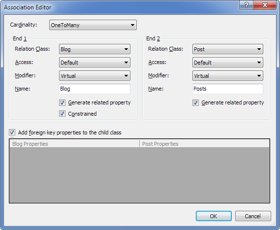
2. In the End 1 area, set Class to Blog and leave other settings at their default values.
3. In the End 2 area, set Class to Post and leave other settings at their default values.
4. In the Cardinality list, select OneToMany.
5. Optional: To create an association using a unique property instead of the primary key, under Foreign key references, select Unique property of Blog and, from the dropdown list, select the required unique property.
6. Optional: To change the default parameters of the database column, in the Columns mapping area, click the ellipsis (…) in the Column field and, in the Column Editor window, enter the desired values and click OK.
7. On the Association editor page, click OK.
For information on how to create other types of associations, see Working with associations.
Create an inheritance
This procedure describes how to create an inheritance. For this procedure, we assume that the Author and RegularAuthor classes have already been created. The inheritance created in this procedure is a table-per-hierarchy (flat inheritance) type.
To create an inheritance:
1. On the model diagram, right-click the Author class and select New Inheritance from the Add submenu.
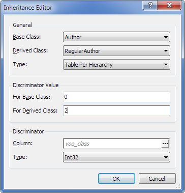
2. From the Base Class dropdown list, select Author.
3. From the Derived Class dropdown list, select RegularAuthor.
4. From the Type dropdown list, select Table Per Hierarchy.
5. In the For Base Class box of the Discriminator Value area, specify the value for the base class (for example, “0”).
6. In the For Derived Class box of the Discriminator Value area, specify the value for the derived class (for example, “1”).
7. In the Discriminator area, from the Type dropdown list, select the appropriate type for the discriminator column. You can change the default column settings by clicking the ellipsis (…) in the Column box and specifying the required values on the Column editor page.
8. Leave the other settings at their default values.
9. Click OK.
Repeat these steps to create the Author - GuestAuthor inheritance.
For more information on how to create inheritances of other types, see Working with inheritances.
Model summary
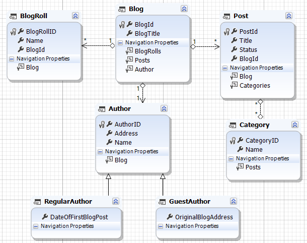
The resulting model should contain the following items:
Classes:
- Blog
- BlogRoll
- Author
- RegularAuthor
- GuestAuthor
- Post
- Category
Associations:
- Blog – Post, Blog - BlogRoll (one-to-many)
- Blog – Author (one-to-one)
- Category – Post (many-to-many)
Inheritances:
- Author – Regular Author
- Author – Guest Author
The following is an example of the resulting model:
Set up mapping and code generation
This section explains how to set up mapping and code generation in Telerik Data Access models.
For mapping and code generation, you may need to create and define folders for the mapping and generated code, and configure other parameters available in the Properties window of the selected template.
Defining output folders is optional. If you don’t need separate folders, go directly to step 11. To define folders for mapping and code generation:
1. In your project in Solution Explorer, create a folder for mapping (for example, Mapping) and a folder for generated code (for example, Entities).
2. In the Model Explorer window, select the template and click to display the Properties window for the selected template.
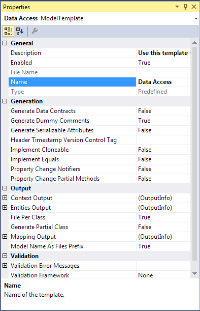
3. In the Output section of the model properties, click the Entities Output line and then click the ellipsis (…).
4. In the Select Project Folder dialog, select the appropriate folder for entities (for example, the Entities folder created in step 1) and click OK.
5. For the File Per Class property, select the appropriate value. If you set a value for the Entities Output parameter, the File Per Class parameter must be set to True.
6. To enable entity property validation, in the Validation section, locate the Validation Framework row and select the appropriate framework. Use the Validation Error Messages row to apply error messages stored in the application resources. For details on validation, see Entity Property Validation.
7. In the Xml Mapping section of the template properties, select the appropriate value for the Xml Mapping Action property to define whether mapping is copied to the folder specified in the Xml Mapping Output parameter, copied to the folder storing the model file if the Xml Mapping Output parameter is not specified, or added to the project as an embedded resource.
8. To generate separate mapping files per class, set the Xml Mapping File Per Class property to True. To generate one mapping file, set it to False.
9. Click the Xml Mapping Output line and click the ellipsis (…) to open the Select Project Folder window.
10. In the Select Project Folder window, select the appropriate folder for entities (for example, the Mapping folder created in step 1) and click OK.
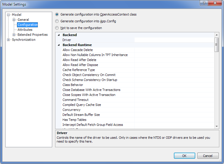
11. Optional: To specify additional parameters for your application (app.config) or web-application (web.config), for example, to change the Proxy Factory setting, right-click the diagram, select Model Settings from the shortcut menu, and in the tree, select Configuration.
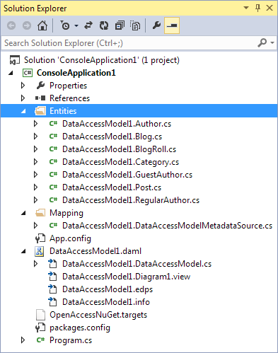
12. To generate code and mapping, save the model. Entities and mapping files are successfully generated and stored in the specified folders:
Update the database from the model
This section explains how to update the database from the model that was created using the Model-First approach. To update the database from the model:
1. Select Tools > Entity Developer > Update Database from Model.
Note
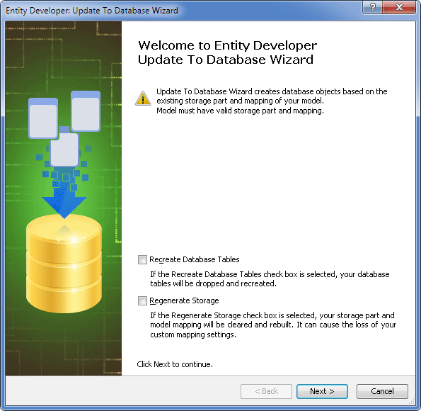
If the Recreate Database Tables checkbox is selected, existing database tables are dropped and created again.
Select the Regenerate Storage checkbox to completely regenerate the Model Storage part and Mapping, including the description of storage columns and relationship ends.
In Telerik Data Access, all customization of column options and other mapping settings are filled automatically by the engine, converting the Conceptual model to the Storage model and Mapping. The engine considers entities, associations, and inheritances from the Conceptual model.
When working with Telerik Data Access, this checkbox is rarely used because the Telerik Data Access runtime doesn’t require the Storage part and Mapping. Use this option only if you want your Storage part to always be complete and automatically generated.
2. Optional: Select the Regenerate Storage checkbox, if appropriate.
3. Click Next.
4. On the Set up data connection properties page, specify the connection parameters for your model and click Next.
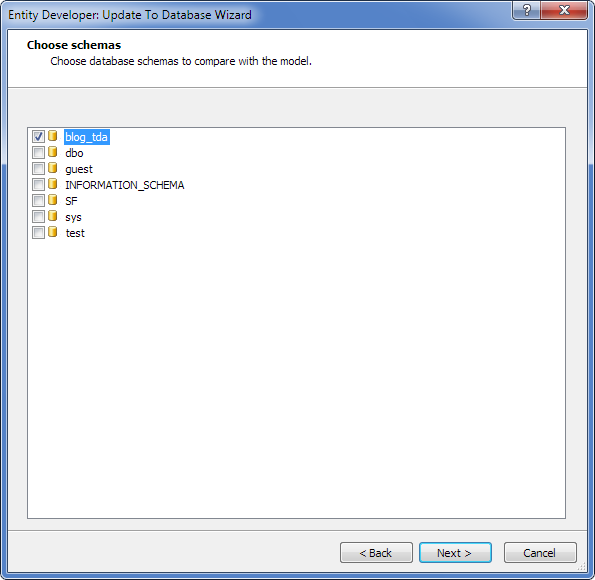
5. On the Choose schemas page, select one or more schemas to be compared and click Next.
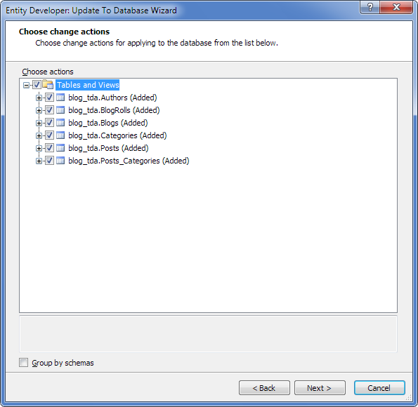
6. On the Choose change actions page, select the appropriate action(s). Use the context menu of the root nodes to check or uncheck all added, dropped, or changed objects. Click Next.
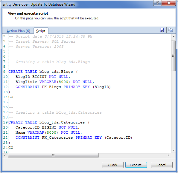
7. On the View and execute script page, click Execute to execute the displayed scripts.
8. On the final window of the wizard, click Finish.
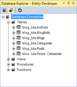
9. To verify the results, select View > Entity Developer and select Database Explorer.
Note
If you want to generate a database object creation script instead, use the Generate Database Script Wizard. For details, see Generate Database Script Wizard.
Test the model
To test the correctness of entities and mapping, enter test data. A sample procedure for entering test data follows.
Enter test data
To enter test data:
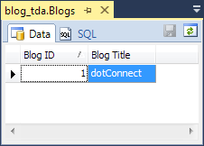
1. In the Database Explorer window, right-click blog_tda.Blogs and select Retrieve data from the shortcut menu.
2. In the Blog Title column of the Data tab, enter dotConnect.
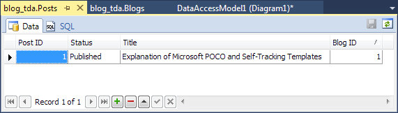
3. In the Database Explorer window, right-click blog_tda.Posts and select Retrieve data from the shortcut menu.
4. Enter the test data.
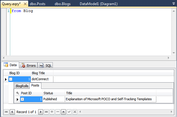
Create and use a new query
After entering test data, create a new query to test the model’s validity. The data returned by the query should match the data you entered previously.
To create and use a query:
1. Select Tools > Entity Developer > New Query.
2. From the Query type dropdown list on the Entity Developer Query toolbar, select HQL.
3. On the Query.eqry tab, enter a new query, for example, “from b in Blogs select b”.
4. On the Entity Developer Query toolbar, click Run Query.
5. View the results of the query.